UK - European distributor, supplier and specialist repairer of FANUC CNC Parts. OEM brand names and trademarks featured are the property of their respective authorised owners and for descriptive purposes only.
A06B-6078-H430
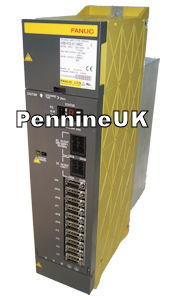
A06B-6078-H430 Fanuc Spindle Amplifier Module
|
A06B-6078-H430 - POA
|
 |
Please phone or email us for availability of this Fanuc Spindle Amplifier Module A06B-6078-H430
We stock the full range of Alpha Spindle Drive's.
All Stock Fanuc Spare Part's carry a Warranty and are available for same day dispatch.
A06B-6078-H430 Technical
A06B-6078-H430#H500
A06B-6078-H430#H501
SPM-30 Type 3 Interface Fanuc Alpha Spindle Module
Next drive in this series A06B-6078-H102
Input voltage 283~325vdc. Output Current Rated at 133Amps.
Type 3 (specifications for spindle switching control or differential speed control)
Applicable detectors :
1. Spindle switching control (switching the speed only, or switching both the speed and position)
2. Differential speed control (input circuit for position coder signals)
Alarms (Red LED)
AL-01: Motor Overheat
AL-02: Excess Speed Deviation
AL-03: Fuse on DC Link Blown
AL-04: Input Fuse Blown
AL-05: Control Power Supply Fuse Blown
AL-06: Overspeed (Analog) (Temperature Sensor Disconnected)
AL-07: Overspeed (Digital)
AL-08: High 24v Input Voltage
AL-09: Overheat Power Semiconductors
AL-10: Low 15v Input Voltage
AL-11: DC Link High Voltage
AL-12: DC Link Overcurrent
AL-13: Data Memory Fault CPU
AL-14: Defective ROM
AL-15: Defective Optional Circuit
AL-16: NVRAM Fault
AL-17: NVRAM Checksum Fault
AL-18: ROM Checksum Fault
AL-19: IU Offset Current Alarm
AL-20: IV Offset Current Alarm
AL-21: VCMD Offset Alarm (Position Sensor Polarity Setting Incorrect)
AL-22: TSA Offset Alarm
AL-23: ER Offset Alarm
AL-24: Serial Transfer Data Error
AL-25: Serial Transfer Stop
AL-26: C Velocity Detector Disconnected
AL-27: Position Coder Disconnected
AL-28: C Position Detector Disconnected
AL-29: Short Period Overload
AL-30: Overcurrent Power Circuit
AL-31: Motor Lock or V Signal Lost
AL-32: Serial communication LSI RAM Error
AL-33: DC Link Pre Charge Failure
AL-34: Parameter Setting Error
AL-35: Gear Ratio Parameter Error
AL-36: Error Counter Overflow
AL-37: Speed Detector Parameter Error
AL-38: x
AL-39: One Rotation Cs Signal Error
AL-40: Cs One Rotation Signal Detection Error
AL-41: Position Coder One Rotation Signal Detection Error
AL-42: One Rotation Position Coder Detected Error
AL-43: Disconnected PC for DIF. SP. MOD.
AL-44: Control Circuit AD Error
AL-45: x
AL-46: Thread Cutting One Rotation Position Coder Alarm
AL-47: Position Coder Signal Abnormal
AL-48: x
AL-49: High Conversion DIF. SPEED
AL-50: Excessive speed command calculation value during spindle synchronization
AL-51: Low Volt DC Link
AL-52: ITP Signal Abnormal 1
AL-53: ITP Signal Abnormal 2
AL-54: Current Overload Alarm
AL-55: Abnormal Switching Status of Power Leads
AL-56: Inner Fanuc Cooling Fan Stopped
AL-57: Excessive Deceleration Power
AL-58: Overload in Fanuc Power Supply Module
AL-59: Cooling Fan Stopped in PSM
AL-60: x
AL-61: x
AL-62: x
AL-63: x
AL-64: x
AL-65: x
AL-66 Communication alarm between spindle and amplifier
AL-67: x
AL-68: x
AL-69: Safety speed exceeded
AL-70: Abnormal axis data
AL-71: Abnormal safety parameter
AL-72: Motor speed mismatch
AL-73: Motor sensor disconnected
AL-74: CPU test alarm
AL-75: CRC test alarm
AL-76: Safety function not executed
AL-77: Axis number mismatch
AL-78: Safety parameter mismatch
AL-79: Abnormal initial test operation
AL-80: x
AL-81: Motor sensor one-rotation signal detection error
AL-82: Motor sensor one-rotation signal not detected
AL-83: Motor sensor signal error
AL-84: Spindle sensor disconnected
AL-85: Spindle sensor one-rotation signal detection error
AL-86: Spindle sensor one-rotation signal not detected
AL-87: Spindle sensor signal error
AL-88: Cooling fan stopped of the radiator
A0: Program ROM error
A1: Program ROM error
A2: Program ROM error
b0: Communication error between amplifier and module
b1: 6 Converter: control power supply low voltage
b2: 8 Converter: excessive regenerative power
b3: A Converter: cooling fan stopped of the radiator
C0: Communication data alarm
C1: Communication data alarm
C2: Communication data alarm
C3: Spindle switching circuit error
Status (Amber LED)
ER-01 SFR (normal rotation command), SRV (reverse rotation command), or ORCM (orientation command) is entered when ESP (emergency stop signal, which may be a input signal or contact signal) and MRDY (machine ready signal) are not applied. Check the sequence of *ESP and MRDY. For MRDY, check bit 0 of parameter No. 4001, specifying whether to use the MRDY signal.
ER-02 When the spindle and Fanuc Spindle Motor are specified separately (with bit 5 of parameter No. 4001 set to 1, and bit 6 of parameter No. 4001 set to 0) in a system employing a high–resolution magnetic pulse coder, 128 /rev must be set for the motor speed detector (bits 2, 1, and 0 of parameter No. 4011 must be set to 0, 0, and 1, respectively). However, a value other than 128 /rev is set. In such a case, the motor is not activated. Check the parameter settings.
ER-03 The Cs contouring control command is input although bit 5 of parameter No. 4001 is set to 0 to specify that a high-resolution magnetic pulse coder is not used or although bit 4 of parameter No. 4018 is set to 0 to specify that the sensor Cs contouring control function is not used. In such a case, The motor is not activated. Check the parameter settings.
ER-04 When bit 2 of parameter No. 4001 is set to 0 to specify that a position coder signal is not used, a command for servo mode control (rigid tapping, Cs axis control, etc.) or spindle synchronization control is entered. In such a case, the motor is not activated.
Check the parameter setting enabling the use of a position coder signal.
ER-05 When the option parameter of the orientation function is not set, ORCM (orientation command) is entered. Check the parameter setting enabling the use of the orientation function.
ER-06 When the option parameter of the speed range switching control function is not set, winding for low–speed characteristics is selected (with RCH =1). Check the setting of the parameter for using the speed range switching control function, and the
power line status check signal (RCH).
ER-07 When the Cs contouring control command is entered, neither SFR (normal rotation command) nor SRV (reverse rotation command) is entered. Check the sequence.
ER-08 When a servo mode control command (rigid tapping, Cs axis control, etc.) is entered, neither SFR (normal rotation command) nor SRV (reverse rotation command) is entered. Check the sequence.
ER-09 When the spindle synchronization control command is entered, neither SFR (normal rotation command) nor SRV (reverse rotation command) is entered. Check the sequence.
ER-10 When the Cs contouring control command is entered, a another mode (such as the servo mode, spindle synchronous control, and orientation) is specified. When Cs contouring control is specified, do not specify another mode. To enter another mode, first cancel the Cs contouring control command.
ER-11 When a servo mode control command (rigid tapping, Cs axis control, etc.) is entered, another mode (such as Cs contouring control, spindle synchronization control, and orientation) is specified. When a servo mode is specified, do not specify another mode. To enter another mode, first cancel the servo mode command.
ER-12 When the spindle synchronization control command is entered, another mode (Cs contouring control, servo mode, or orientation) is specified. When spindle synchronization control is specified, do not specify another mode. To enter another
mode, first cancel the spindle synchronization control command.
ER-13 When the orientation command is entered, another mode (Cs contouring control, servo mode, or spindle synchronization control) is specified. When orientation is specified, do not specify another mode. To enter another mode, first cancel the orientation command.
ER-14 SFR (normal rotation command) and SRV (reverse rotation command) are entered at the same time. Specify only SFR or SRV at one time.
ER-15 When bit 5 of parameter No. 4000 is set to 1 to specify the use of the differential speed control function, the Cs contouring control command is entered. Check the parameter setting and input signal.
ER-16 When bit 5 of parameter No. 4000 is set to 0 to specify that the differential speed control function is not used, DEFMD (differential speed mode command) is entered. Check the parameter setting and the differential speed mode command.
ER-17 The setting of bits 2, 1, and 0 of parameter No. 4011 for specifying a speed detector is incorrect. The specified speed detector cannot be found. Check the parameter setting.
ER-18 When bit 2 of parameter No. 4001 is set to 0 to specify that a position coder signal is not used, orientation by a position coder is specified. Check the parameter setting and input signal.
ER-19 When orientation by a magnetic sensor is specified, another mode (Cs contouring control, servo mode,
or spindle synchronization control) is specified. When orientation is specified, do not specify another mode. To enter another mode, first cancel the orientation command.
ER-20 When bit 5 of parameter No. 4014 is set to 1 to specify use of the slave operation function, bit 5 of parameter No. 4001 is set to 1 to specify use of a high resolution magnetic Fanuc pulse coder. The use of the slave operation function and that of a high resolution magnetic pulse coder cannot be specified at the same time. Check the parameters settings.
ER-21 In a position control mode (servo mode, orientation, etc.), SLV (slave operation command) is entered. Enter the slave operation command in normal operation mode only.
ER-22 In slave operation mode, a position control command (servo mode, orientation, etc.) is entered. Enter a position control command in normal operation mode only.
ER-23 When bit 5 of parameter No. 4014 is set to 0 to specify that the slave operation function is not used, SLV (slave operation command) is entered. Check the parameter setting.
ER-24 In continuous indexing with orientation by a position coder, incremental operation (INCMD = 1) is first performed, after which the absolute position command (INCMD = 0) is entered. Check INCMD (incremental command). Before specifying absolute position commands in succession, perform absolute position command orientation.
ER-25 Bit 4 of parameter No. 4018 is set to 1 to enable the sensor Cs contouring control function although SPM TYPE 4 is not selected. Check the parameter setting and SPM drawing number.
|
Fanuc Drive Type |
Fanuc SPM Type |
Applicable Fanuc Motor |
|
SPM-2.2 |
A0.5, A1 |
|
|
SPM-5.5 |
A1.5, A2 |
|
|
SPM-11 |
A6, A8, AP8, AP18 |
|
|
SPM-2.2 |
A0.5, A1 |
|
|
SPM-5.5 |
A1.5, A2 |
|
|
SPM-11 |
A6, A8, AP8, AP18 |
|
|
SPM-2.2 |
A0.5, A1 |
|
|
SPM-5.5 |
A1.5, A2 |
|
|
SPM-11 |
A6, A8, AP8, AP18 |
|
|
SPM-11 |
A6, A8, AP8, AP18 |
|
|
SPM-15 |
A12, AP15, AP18 |
|
|
SPM-22 |
A15, A18, AP22, AP30 |
|
|
SPM-26 |
A22, AP40, AP50 |
|
|
SPM-30 |
AP30 |
Shipping Details
Find and order Fanuc CNC machine spares with just a few clicks from wherever you are. Same or next day service on stock. NEW & Obsolete Fanuc. Also, Repair Fanuc and Fanuc support for CNC products we sell.
We use UPS are our preferred courier. By doing so, we are able to offer delivery to more than 90% of the UK with a next-working-day delivery service*, including vital tracking functionality and POD information. Items shown as 'in stock' and confirmed as ordered by 3 pm Mon-Thu and 12 pm Fri (excluding Bank Holidays) can be delivered the next working day. (Subject to availability and shipping restrictions). For urgent orders, we can also offer a same day delivery service - please speak to our dedicated customer service team about this option.
UK Shipments. We can offer same day delivery and timed next day deliveries to most places in the UK, This is just a small list of places included: Newcastle, Sunderland, Barrow, Carlisle, York, Bradford, Leeds, Huddersfield, Huddersfield, Manchester, Swindon, Sheffield, Hull, Lincoln, Chester, Stoke, Nottingham, Norwich, Birmingham, Coventry, London, Northampton, Oxford, Dover, Portsmouth, Southampton, Liverpool, Bournemouth, Torquay, Plymouth, Newquay, Bristol, Ruislip, Middlesex, Scotland, Glasgow, Edinburgh, Stafford, Swansea, Cumbria, Cardiff, Lincolnshire, Yorkshire
Most Fanuc European Locations, We can offer next day delivery to the following locations in Europe.** We also may be able to offer a before 12 pm Service (dependent on location).
Austria, Belgium, Czech Republic, Denmark, Deutschland, Dublin, Finland, Fanuc Francais, Germany, Hungary, Ireland, Italy, Luxembourg, Monaco, Netherlands, Poland, Slovenia, Spain, Sweden.
Rest of the World and European destinations, 1-2 days estimated shipment.**
United States, Canada, Mexico, Bulgaria, Cyprus, Crete, Estonia, Iceland, Latvia, Lithuania, Switzerland, Portugal, Norway, Albania, Bosnia, Belarus, Croatia, Montenegro, Russia, Turkey, Ukraine
Rest of the World 2-4 Day estimated shipment.**
Australia, New Zealand, Bangladesh, Indonesia, Philippines, Saudi Arabia, UAE, The Middle East, Africa, Central America, and the Caribbean.
* UPS services are subject to delivery exception areas detailed below:
AB12, AB37, AB38, AB44, AB45, AB53, AB54, AB55, AB56, CA18, CA19, CA20, CA21, CA22, CA23, CA24, CA25, CA26, CA27, HS1, HS2, HS3, HS4, HS5, HS6, HS7, HS8, HS9, IM, IV10, IV11, IV12, IV14, IV15, IV16, IV17, IV18, IV19, IV20, IV21, IV22, IV23, IV24, IV25, IV26, IV27, IV28, IV30, IV31, IV32, IV36, IV40, IV41, IV42, IV43, IV44, IV45, IV46, IV47, IV48, IV49, IV50, IV51, IV52, IV53, IV54, IV55, IV56, IV7, IV9, KA27, KA28, KW, LA15, LA16, LA17, LA18, LA19, LA20, LA21, LA22, LA23, PA20, PA21, PA22, PA23, PA24, PA25, PA26, PA27, PA28, PA29, PA30, PA31, PA32, PA33, PA34, PA35, PA36, PA37, PA38, PA41, PA42, PA43, PA44, PA45, PA46, PA47, PA48, PA49, PA60, PA61, PA62, PA63, PA64, PA65, PA66, PA67, PA68, PA69, PA70, PA71, PA72, PA73, PA74, PA75, PA76, PA77, PA78, PA80, PA81, PA82, PA83, PA84, PA85, PA86, PA87, PA88, PH17, PH18, PH19, PH20, PH21, PH22, PH23, PH24, PH25, PH26, PH30, PH31, PH32, PH33, PH34, PH35, PH36, PH37, PH38, PH39, PH40, PH41, PH42, PH43, PH44, PH49, PH50, TR21, TR22, TR23, TR24, TR25, ZE. Please speak to us if you require express delivery to these areas.
**DAP – Delivered at Place (named place of destination). CNC Spares and Repairs Limited shipping costs cover carriage to the place named by the customer at the time of purchase, except for any costs related to import clearance. Import clearance = import duty and VAT.
Contact | A03B | A14B | A16B | A20B | A80L | A81L | Fanuc Drive | Fanuc uk | Fanuc Repairs | Beta Servo
Enquiry Form
© 2022 UK Independent FANUC Parts Online. All rights reserved. We are NOT affiliated to Fanuc Ltd. All trademarks are acknowledged. XML Sitemap


